
Project: Circuit Designer (Electrical Modality for LLMs)
1. Executive Summary
The goal of this project is to provide Large Language Models (LLMs) with an “Electrical Modality.” Just as LLMs can
generate and execute Python code to solve math problems, this system allows LLMs to design, visualize, and verify analog
circuits.

The system relies on a Central Intermediate Representation (CIR). The LLM generates a single JSON definition containing the circuit topology, spatial layout, and verification requirements. This JSON is then compiled into two distinct outputs:
- Simulation: An
eecircuit.js(SPICE) model to verify performance against defined test cases. - Visualization: A
tscircuitrendering to provide interactive schematics and PCB layouts.
2. Architecture Overview
graph TD
    User[User Prompt] --> LLM[LLM]
    LLM --> CIR[CIR-JSON]

    subgraph "The Runtime"
        CIR -->|Compiler A| Sim[Simulation Engine \neecircuit]
        CIR -->|Compiler B| Viz[Visualization Engine \ntscircuit]
        Sim -->|Raw Data| Verifier[Test Case Verifier]
        CIR -->|Assertions| Verifier
    end

    Verifier -->|Pass/Fail + Logs| Feedback[Result Summary]
    Viz -->|Canvas Draw| UI[User Interface]
    Feedback --> UI
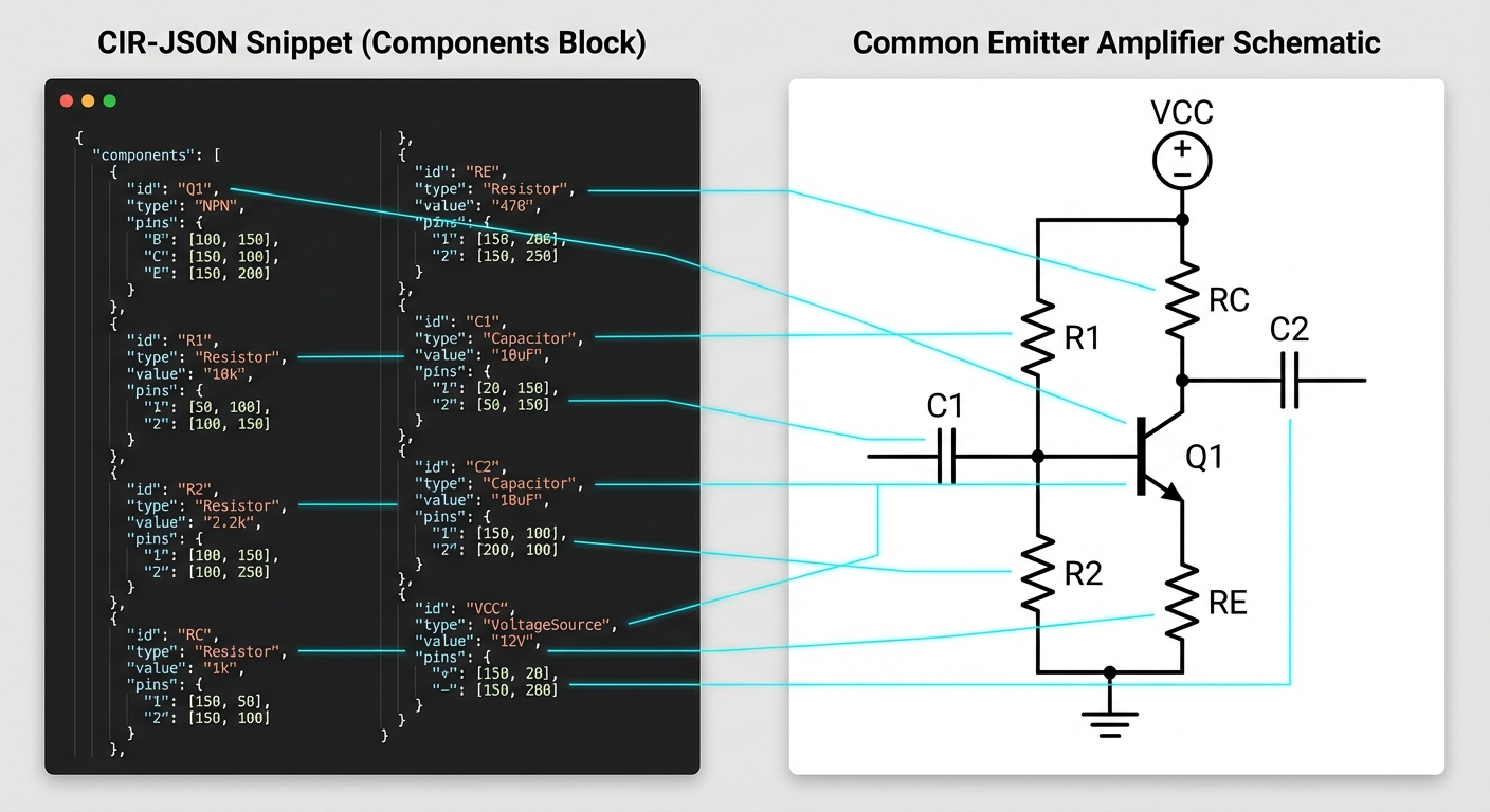
3. The Central Intermediate Representation (CIR-JSON)
To avoid “split-brain” issues (where the simulation and diagram disagree), the LLM generates a single source of truth. We leverage the LLM’s modern capability for spatial reasoning to define layout coordinates directly, rather than relying on a complex auto-router.
Schema Definition
1
2
3
4
5
6
7
8
9
10
11
12
13
14
15
16
17
18
19
20
21
22
23
24
25
26
27
28
29
30
31
32
33
34
35
36
37
38
39
40
41
42
43
44
45
46
47
48
49
50
51
52
53
54
55
56
57
58
59
60
61
62
63
64
65
66
67
68
69
70
71
{
  "meta": {
    "title": "Common Emitter Amplifier",
    "description": "Gain of approx 10, cutoff 20Hz"
  },
  "config": {
    "ground_node": "0",
    "supply_voltage": "12V"
  },
  "components": [
    {
      "id": "Q1",
      "type": "BJT_NPN",
      "model": "2N2222",
      "connections": {
        "C": "N_COL",
        "B": "N_BASE",
        "E": "N_EMIT"
      },
      "layout": {
        "x": 400,
        "y": 300,
        "rotation": 0,
        "mirror": false
      }
    },
    {
      "id": "R1",
      "type": "RESISTOR",
      "value": "10k",
      "connections": {
        "p": "VCC",
        "n": "N_BASE"
      },
      "layout": {
        "x": 400,
        "y": 150,
        "rotation": 90
      }
    }
  ],
  "wires": [
    {
      "points": [
        [
          400,
          150
        ],
        [
          400,
          300
        ]
      ]
    }
  ],
  "simulation": {
    "type": "transient",
    "params": {
      "step": "10us",
      "stop": "10ms"
    }
  },
  "test_cases": [
    {
      "name": "Gain Verification",
      "expression": "max(V(N_COL)) / max(V(N_BASE))",
      "condition": "> 8",
      "description": "Ensure voltage gain is at least 8x"
    }
  ]
}
4. Simulation & Verification Strategy (eecircuit)
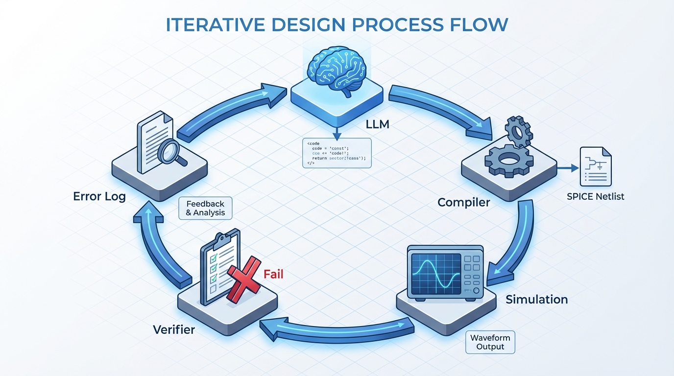
We treat circuit design like software engineering: Test-Driven Design. The LLM must not only build the circuit but define how to prove it works.
4.1 The Compiler (CIR $\to$ SPICE)
A utility function transforms the CIR-JSON into the object/string format required by eecircuit.
- Netlist Generation: Iterates through
componentsto build SPICE lines (e.g.,R1 VCC N_BASE 10k). - Model Injection: Injects standard models for transistors/diodes if referenced (e.g.,
.model 2N2222 NPN...). - Source Injection: Automatically adds the input signal source defined in the prompt or config.
4.2 The Test Runner
Once eecircuit completes the simulation, it returns a data array (time, voltages, currents). The Test Runner
evaluates the test_cases defined in the JSON.
Supported Assertions:
- DC Operating Point:
V(node) approx 5V(useful for biasing checks). - Peak-to-Peak:
pkpk(V(out)) > 2V. - Frequency:
freq(V(out)) == 1kHz. - Logic Levels:
min(V(out)) < 0.5V(for digital/switching).
Feedback Loop:
If a test fails (e.g., “Gain was 2.1, expected > 8”), this specific error string is fed back to the LLM for the next
iteration, allowing it to tune component values.
5. tscircuit for Visualization
We have selected tscircuit (TypeScript/React Circuit) to replace schematic.js. This represents a shift from a
static canvas approach to a modern, component-driven architecture.
Strategic Advantages:
- React Ecosystem:
tscircuitallows circuits to be defined as React components. This enables a declarative workflow where the “Compiler B” transforms CIR-JSON into a React component tree (e.g.,<Resistor />,<Capacitor />). - Hybrid Layout Engine: While the LLM can provide coordinates,
tscircuitpossesses powerful auto-routing capabilities. We can make thelayoutblock in CIR-JSON optional, allowing the LLM to focus on topology whiletscircuithandles the aesthetic routing (“Schematic-as-Code”). - PCB Readiness:
tscircuitis designed to generate PCB fabrication files (Gerbers). This expands the project scope from “Circuit Designer” (Schematic) to “Hardware Engineer” (Schematic + PCB Layout). - Interactive DOM: Unlike the static canvas of
schematic.js,tscircuitrenders interactive SVG/HTML elements. This allows for features like hovering over a wire to see its voltage (from the simulation results) or clicking a component to edit its value.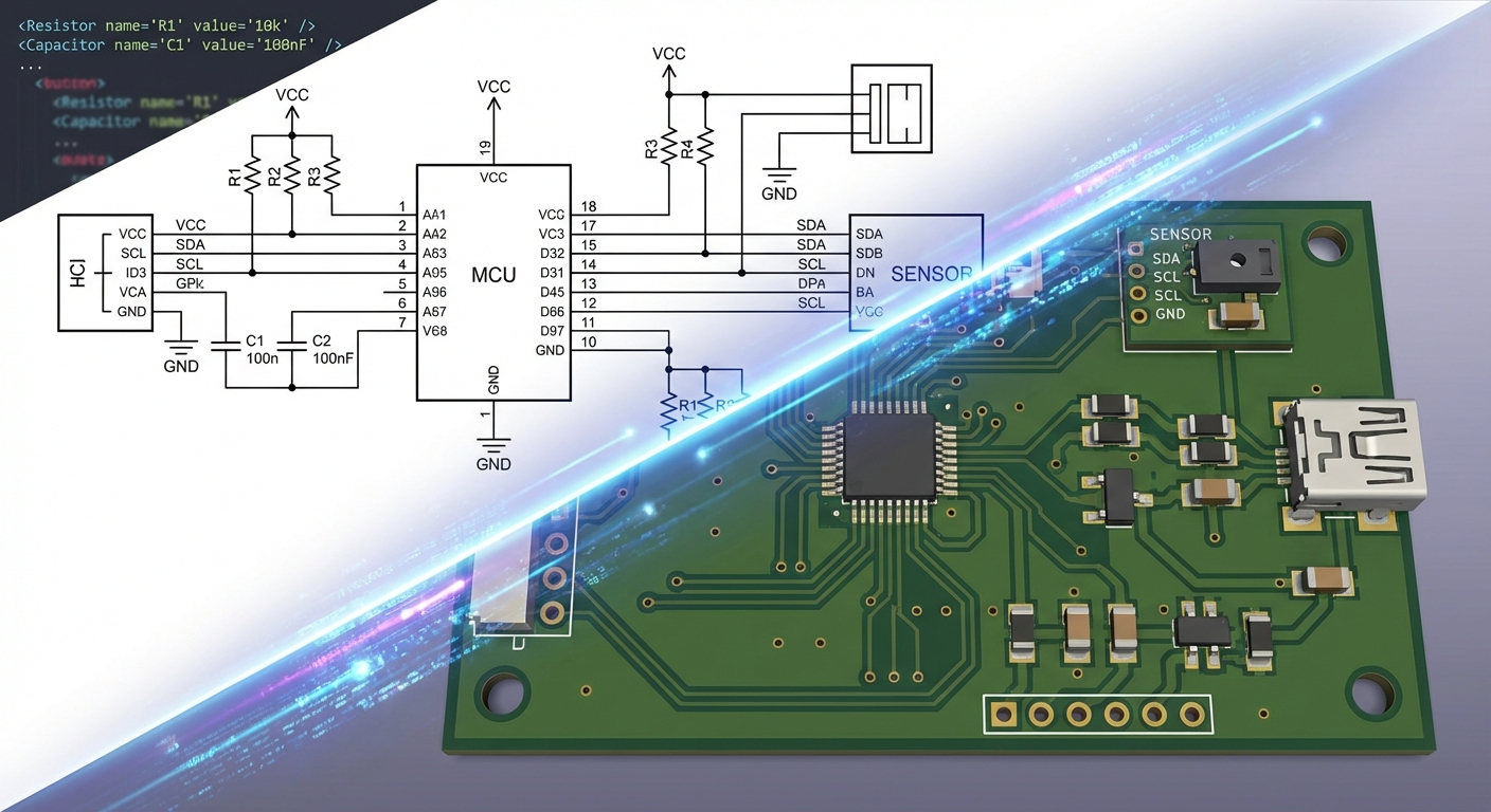
Implementation Plan:
- Step 1: Create a transformer that maps CIR-JSON components to
tscircuit“Soup” (its internal JSON IR) or directly to React Element props. - Step 2: Integrate the
tscircuitschematic viewer into the frontend. - Step 3: Investigate
tscircuit’s emerging simulation support to potentially unify the Simulation and Visualization engines into a single dependency.
6. Expanded Capabilities & Ideas
With the adoption of tscircuit, several advanced features become feasible:
6.1 Interactive “Live” Schematics
Because the schematic is rendered as a React component tree, we can inject simulation results directly into the visual layer.
- Voltage Heatmaps: Wires change color based on voltage levels (Red = High, Blue = Low).
- Current Flow Animation: Animated dashes along wires indicating current direction and magnitude.
- Click-to-Tune: Users can click a resistor, change
10kto20kvia a UI popup, and the system re-runseecircuitimmediately, updating the graphs.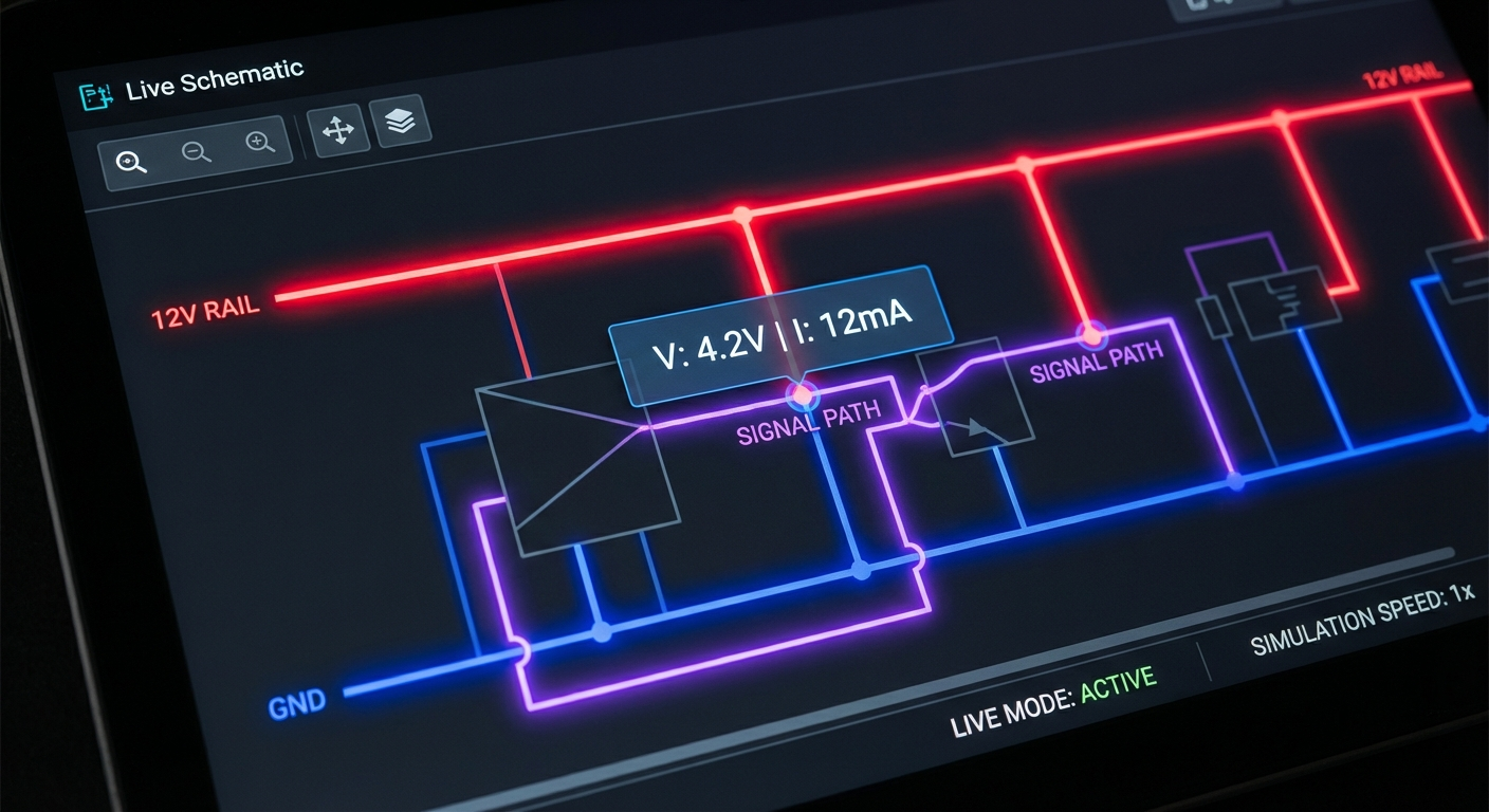
6.2 Real-World Part Selection
tscircuit integrates with part supply chain data.
- Instead of a generic “NPN Transistor”, the LLM can select a specific “JLCPCB Part #C12345”.
- The system can generate a Bill of Materials (BOM) with pricing and availability.